|
|
|
|
|
|
|
|
|
|
|
|
Last update :
14. 4. 2016 000 11:31
|
|
|
|
|
FAULT SIGNALLING |
|
|
|
| POR 32 FAULT SIGNALLING MODULE
|
It is designed to signal faults of the technological process by means of LED diodes.
|
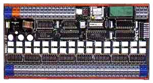 |
| The module contains: |
| | 32 optically separated inputs |
| | 32 outputs for LED |
| | a microprocessor |
| | an output for control of audible signalling device |
| | a switch voltage regulator tube for regulation of supply potential |
|
| Motorola microprocessor provides ordinary fault signalling: |
| | activation of the audible signalling device if a fault is detected |
| | flickering if an emergent fault is detected |
| | lightening if the fault is accepted by an operator |
| | LED performance test |
|
|
|
for larger fault signalling system any number of these modules in a cascade can be used, controlled by one set of control buttons (accept button, audible signalling device switch off, LED performance test). Flickering and frequency is synchronized on all modules. |
|
an amplification relay of the audible signalling device and a coupler are used on the first module in the cascade (master). The coupler determines that the master works as a source of flickering frequency. |
|
input terminal WAGO is appropriate for cables with up to 2,5 mm2 cross-section. |
|
the output side is equipped with 32 two-pole connectors for connection of one-colour LED diodes. LED diodes are activated in a multiplex mode and are placed in 8 clusters with 4 LED diodes. |
|
output circuits control red, yellow and green LED; it is impossible to control devices with series connection of several luminous chips. |
|
range of supply voltage : 15 - 36 V DC |
|
module power consumption: max. 3,6 W |
|
input voltage: from 5 to 60 V DC |
|
input current: 10 mA |
|
separating relay, operating on 6A, 250 V AC, is connected to the amplification relay of the audible signalling device |
|
it is possible to activate a piezoelectric siren without the amplification relay with power consumption max. 0,1 A, 5 V. |
|
mounting on the D-IN bar |
|
module weight including D-IN bar holder: 0,12 kg |
|
module dimensions : 190 x 100 mm |
|
| up |
|
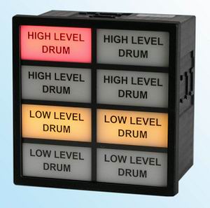
| DISPLAY FOR FAULT INDICATION
|
The display is designed for co-operation with POR 32- fault signalling module.
|
 |
|
it is possible to connect 4 displays for fault indication to 1 POR32 module. Each display can indicate 8 faults. It is possible to choose, which group of faults will be indicated, by means of a switch on the back side of the display. |
|
The display and the module are connected by 16wire flat cable with connectors. The maximal length of the connecting cable is 2 m. |
|
Transillumination of every fault is provided by 2 LED diodes. The diodes are placed in connectors, which enable their easy replacement. |
|
The colour of transillumination can be red or yellow in accordance to diodes used. The light of the highly shining LED diodes is homogenized by a ground-glass, on which there is a label with a description of faults. |
|
|
The description is made by a laser printer on a transparent plastic foil. The descriptions of all the faults of one display are on one label. The label is covered by Perspex with an antireflection coating from the front side. The Perspex can be removed after removal of display case frame. |
|
|
The display is mounted in a standard case (DIN) with front face 96 x 96 mm and depth 63 mm. A field 45 x 20 mm is available for each fault. |
|
|
| up |
|

|
|
|
Jiraskova 31
506 01 Jicin
Czech Republic
phone:+420 493 532 352
fax:+420 493 534 931
e-mail: apel@apel.cz
|
|
|
|