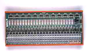
| D-IN INPUT MODULE |
 |
|
this module regulates input signals for one- or two- colour LED diodes. It features circuits for a LED performance check, which enables to check all microchips at the same time. |
|
the input terminal board WAGO is available for cables with up to 2,5 mm2 cross-section. |
|
the output side is equipped with 12 three-pole connectors for a connection of two-colour LED diodes. |
|
the standard voltage : 24 V DC. The current 10 mA is set for this voltage. |
|
the range of the voltage: 15 - 30 V DC |
|
|
the signal contact with joint plus - a contact loading for the LED performance check is reduced with a transition amplifier (an input current 10mA) |
|
mounting on a DIN bar |
|
|
a possibility to supply the modem D-IN for another voltage : from 5 to 60 V DC. |
|
the module weight including a DIN bar holder : 0,12 kg |
|
the module dimensions: 165 x 75 mm |
|
|
| up |
|
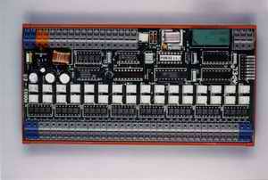
| POR32 FAULT SIGNALLING MODULE |
|
The module contains:
32 optically separated inputs
32 outputs for LED
microprocessor
output for control of audible signalling device
switch voltage regulator tube for regulation of supply potential
|
|
The module is designed to signalise faults of technological process by means of LED diodes.
|
For more information please click here
|
|
 |
| up |
|
| CONNECTOR MODULES |
|
connection with modules, e.g. D-IN or POR32, through three-pole connectors accessible from the rear side of the module. |
|
modules are fixed to the rear side of the grid |
|
LED diodes are put in the connectors from the front |
|
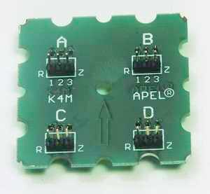
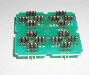
| Type K4M |
 |
|
the display module enables to use 4 two-colour LED diodes in the 24 mm grid |
|
dimensions: 48 x 48 mm |
| Type K9 |
|
the display module enables to use 9 two-colour LED diodes in the 8mm grid |
|
dimensions: 24 x 24 mm |
| Type K16M |
|
this module enables to use 16 two-colour LED diodes in the 12 mm grid. It is possible to use couplers PR1 and PR16 that connect LED diodes cathodes to reduce the number of the needed conductors in the panel. |
|
dimensions: 48 x 48 |
|
| Type K16R |
 |
|
this module has connectors placed in four clusters; each cluster contains 4 two-colour LED diodes that are placed in cross with a vertical and a horizontal leg. The clusters are in 24 mm grid. It is possible to use couplers PR1 and PR16 that connect LED diodes cathodes to reduce the number of the needed conductors in the panel. |
|
dimensions: 48 x 48 |
| Type K16P |
|
this module is a variant of the module K16R. Both anodes of red and green LED diodes in every cluster on the horizontal leg are closely connected in parallel. An analogous connection is on the vertical leg. The cathodes of all 16 LED diodes are connected. This modification reduces the number of conductors in the panel. |
|
dimensions: 48 x 48 mm |
|
| up |
|
| RE 12 GALVANIC SEPARATION MODULE |
|
module contains 12 separating (amplification) relays |
|
relay coils are bridged with suppression diodes - one coil tag is connected to a common terminal (-) |
|
the second coil tag is connected to a terminal board |
|
the circuit-closing contact of each relay is connected to two terminals separately |
|
it is possible to put a 13th relay on the module. This relay checks supply voltage of e.g. coils of other relays and switches on the LED if supply voltage disappears. Independent power supply 24 V AC is used for signalling. |
|
standard supply voltage of relay coil: 24 V DC |
|
coil current: 22 mA |
|
contact switch capacity: 12 A, 250 V AC |
|
test voltage coil - contact: 4 kV |
|
mechanical durability: 30 x 106 contact making |
|
input and output terminal board WAGO is available for cables with up to 2,5 mm2 cross-section. |
|
mounting on a DIN bar. |
|
module dimensions : 165 x 75 mm |
|
| up |
|
| O-IN 16 OPTIC SEPARATION MODULE |
|
this module is used for optic separation of the input signals in bistable signalling by means of LED diodes |
|
the input signal is single-point information |
|
the positive pole is common for all inputs, negative pole activates inputs |
|
independent input for LED performance test |
|
module outputs are compatible with D-IN module. Module is usable in conjunction with connector modules. |
|
it is possible to change interpretation of LED signalling by means of couplers setting |
|
standard input voltage: 24 V DC and 5 V DC for test |
|
power supply: 5 V DC |
|
maximal take-off: 200 mA |
|
number of inputs: 16 |
|
input voltage (based on regulation): from 5V to 48 V DC |
|
maximal current input: 15 mA |
|
insulating voltage: 5000 V |
|
module dimensions: 165 × 75 mm |
|
| up |
|
| OP-IZ200 |
|
this module transfers input voltage 220 V DC to 24 V DC |
|
inputs and outputs - galvanic separation |
|
LED indicates the attendance of input signals |
|
input rated voltage: 220 V DC |
|
input current: 3 mA |
|
output: 15 mA, source of power |
|
input power supply: 24 V DC ± 10% |
|
input and output terminal board WAGO is available for cables with up to 2,5 mm2 cross-section |
|
mounting on a DIN bar |
|
module weight including a DIN bar hanger : 0,1 kg |
|
module dimensions: 48 x 96 x 60 mm |
|
|
| up |